 Got a question? We’re here to help!
|
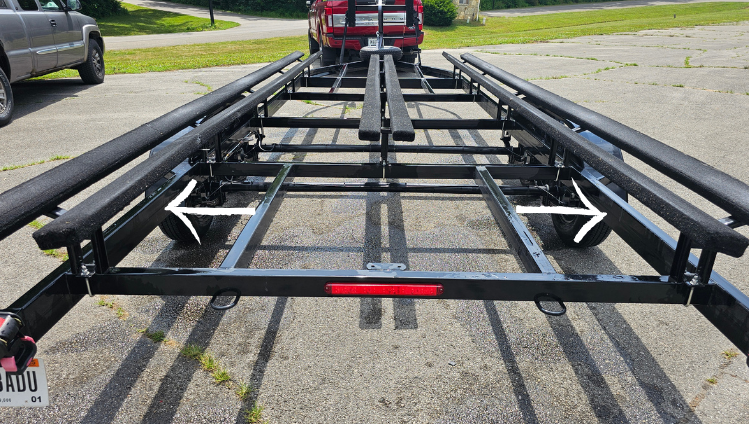
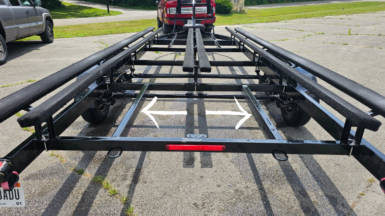
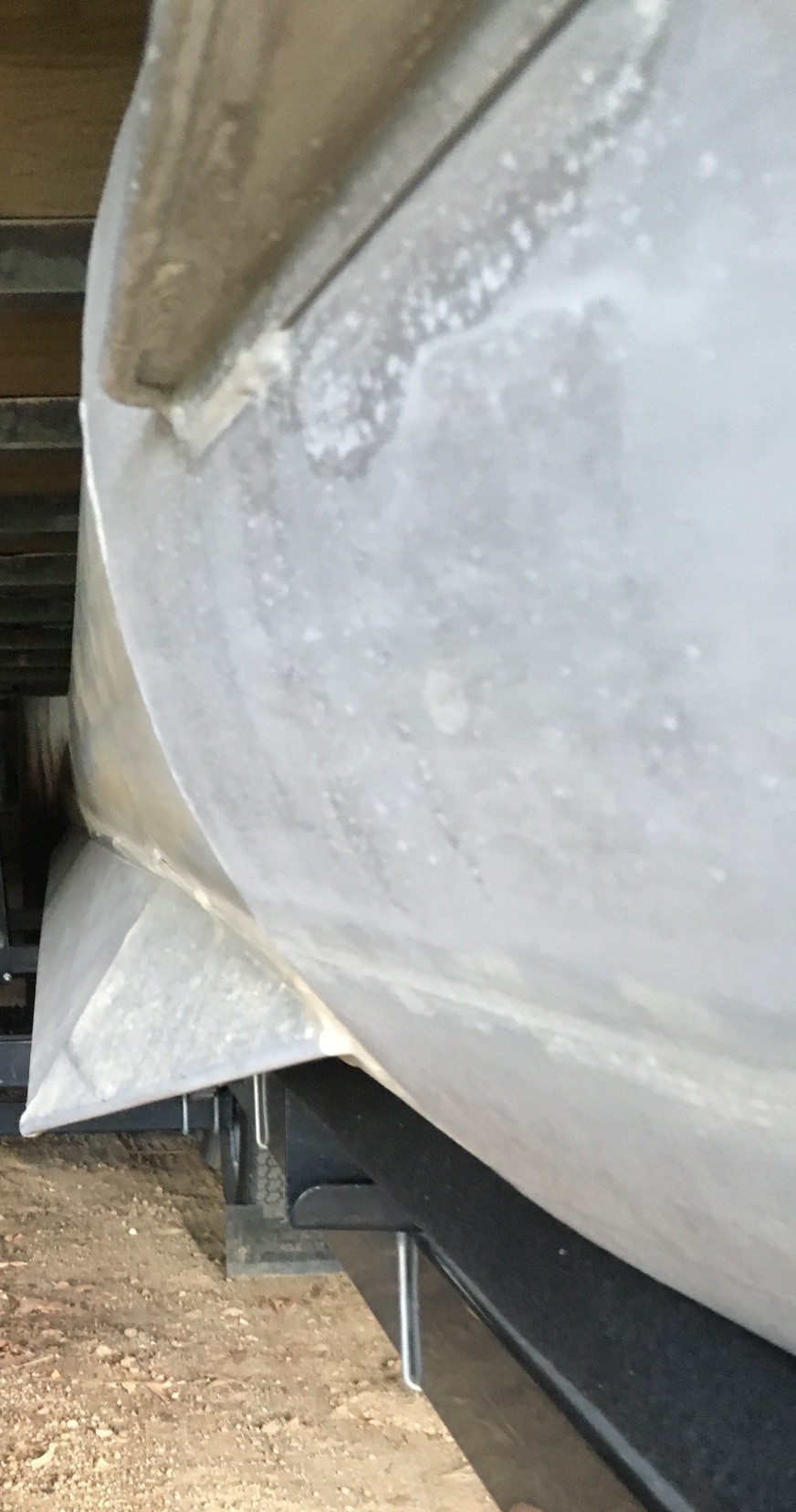
Our CMC Loader Rails are angled-raised in the back. This allows the back of the pontoon logs to stay in the correct position. No more floating or drifting around getting out of position. Causing a crooked load or a complete misload. Our guide rails are 100% from front to back above the water line. This ensures loading is easy. Works really well on long pontoons. Because boats vary in size, the distance between support rails may vary and the distance between the guide rails may vary as well. This variance may depend on the distance between pontoons and the boat. The guide rails are spaced and sized to fit within the cavity between the pontoons of the pontoon boat. The height of the guide rails may vary as well depending on the height of the pontoons. For example, the guide rail can not be so high as to prevent the pontoon from resting on the support rail but should be high enough at the rear of the trailer to extend above the water when the trailer is backed down a ramp for loading. As shown in illustration (A), you can see the pontoon would be hard to load under these conditions. However, you can see in illustration (B) that our loader rails would allow correct loading every time. SPEND LESS TIME LOADING YOUR PONTOON, and no more guessing if it’s loaded on straight. Comes with all mounting hardware. |
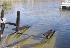 ILLUSTRATION (A) Trailer without CMC Loader Rails 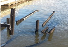 ILLUSTRATION (B) Trailer with CMC Loader Rails |
|
CMC Loader Standard Kit Assembly is Made from Unpainted Aluminum. All mounting hardware zinc-plated steel. 1. 2 pcs 106.00″ Angle Rails Assembly 2. 2 pcs Front Out Rigger to Main Trailer Frame Assembly 3. 2 pcs Rear Out Rigger To Main Trailer Frame Assembly 4. 2 pcs Front Upright Pole Assembly 5. 2 pcs Rear Upright Pole Assembly 6. 2 pcs Front Upright Plate U-bolt Assembly 7. 4 pcs rear upright plates 8. 1 pc angle rear cross over 9. 12 pcs 3.8″x1.5″ Leg Screws |
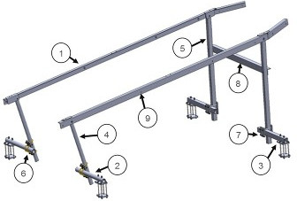 HOW IT ATTACHES |
|
Our CMC Loader Rails are designed to take on high winds and impact. Our rails have over eight feet of contact with the logs. This allows the pontoon to load straight with your trailer. Works with large and small pontoons. In illustration (C) and (D), we show the relationship to a boat ramp and the water line. As noted previously, the guide rail has a higher height near the rear of the trailer than near the center of the trailer. The benefit of this configuration can be seen in relationship to the water line. In illustration (D), we see what happens when the trailer is backed down a ramp for loading (or unloading). The rear portion of the trailer is submerged underwater so that the guide rail must be higher near the rear to remain above the water line. In illustration (C), we see how other products remain below the water line, allowing the rear of the pontoon to move around. One way to accomplish the configuration depicted in illustration (D) ie slope of ramp by adjusting front uprights support members. The support member near the center of the trailer is shorter than the support member near the rear of the trailer. The specific height of those support members can be selected based on the size of the pontoons, the length of the trailer, and the slope of the ramp. The goal is to have the rear portion of the support rail at or above the water line when the trailer is positioned on a boat ramp as shown in illustration (D). With the guide rail configured as shown, a boat can approach the trailer and come in contact with the guide rail very early in the boat loading process. Accordingly, the boat will be aligned with the support rails very early in the loading process as well. With that confidence a user can approach the trailer at a speed and certainty that allows them to drive the boat almost completely onto the trailer without the assistance of a third party in the water. As shown in illustration (E), our rails are also angled in the back to ensure loading will be done by the rails and take the stress off the operator. Our CMC Loaders are also designed to fit tri-toons. Visualization
|
 ILLUSTRATION (C)  ILLUSTRATION (D) 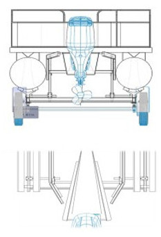 ILLUSTRATION (E) 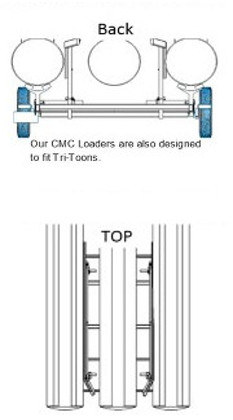 ILLUSTRATION (F) |
|
By upgrading to our deluxe loading system you will experience a whole new way of getting out of the water. It’s Load, Latch, and Go Home. The auto latch assembly is made from heavy duty unpainted aluminum, with the exception of the lower assembly which is made from flat black painted steel. Latch ships with all mounting hardware included. Please note it must be installed with our CMC Loader Rails and is not sold separately. One benefit of having the guide rails designed as previously discussed is that the person loading the boat can approach the trailer with speed and confidence. This allows the boat, in most cases, to be driven up onto the trailer without the assistance of another person in the water. Because of this, a latch system is beneficial to secure the boat on the trailer. In illustration (A), we see the trailer has a post near the frotn to which an exemplary latch system can be attached. As the boat is driven up onto the trailer, a component of the boat operates the latch system such that the boat is securely help on the trailer. Our CMC Auto Latch includes a component that is attached to the underside of the deck of the boat. In describing the latch, the front of the latch is considered to be the portion of the latch that first comes in contact with the boat. To understand the operation of the latch, it must be remembered that the boat is mainly supported by the support rails of the trail. Thus, the height of the latch system is adjusted on the post to engage the striker arm assembley. In operation, a boat approaches the latch system and comes in contact with the front edge portion. Once the striker slips past the corner of the front edge portion, there is no longer any downward pressure on that front portion. So the main body is able to pivor back up. As a result, the striker assembly is latched into the opening. To release the latch when it is time to unload the boat in th ewarer, simply move the handle which rotates the main body. |
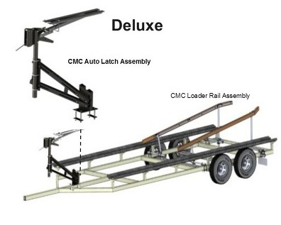 ILLUSTRATION A  Our system should be on every pontoon. |
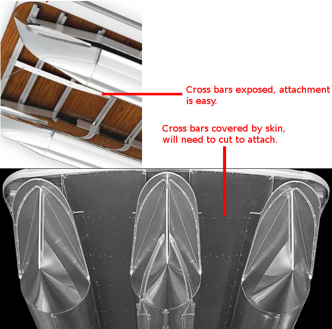
Front Latch Underside Attachment Requirements

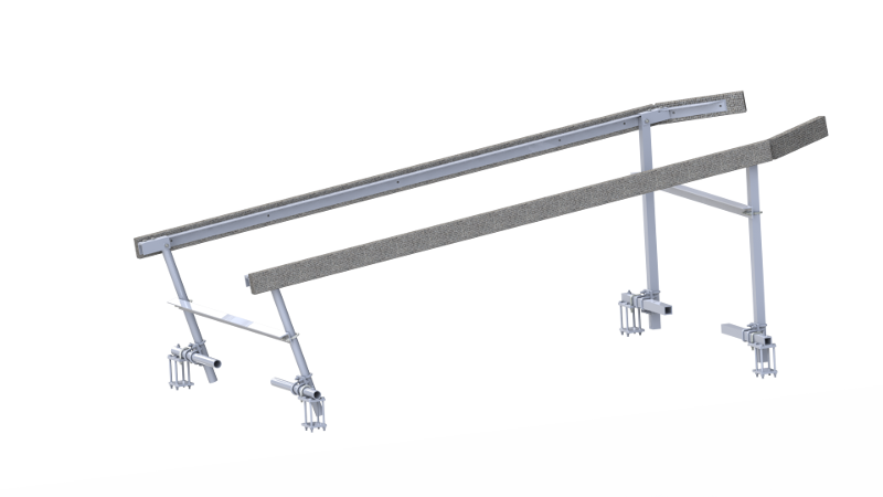
Close up: 2×4 Carpeted Rail Kit Add-on. Carpet is already attached to the 2×4’s and add-on kit comes the carriage bolts pre-installed. Image shows carpeted rails attached to the standard rail kit.